

A welding fume extraction system should not be judged by the size of the collector alone. Welding fume is generated at the arc, moves as a hot plume, and changes direction with part position, welder posture, shielding gas, cross-drafts, and the shape of the fixture. If the hood, arm, or enclosure does not follow that plume, the collector may run all day while the welder still works in visible fume.
The practical question is not "how many cubic feet per minute can the fan move?" The first question is "where does the fume travel during the real weld?" OSHA guidance on welding fume control emphasizes keeping fume hoods, fume extractor guns, and vacuum nozzles close to the plume source. NIOSH field work on local exhaust ventilation also shows that correct positioning and adequate exhaust flow are central to performance. Those are work-cell questions before they are equipment questions.
The Weld Plume Is the Design Target
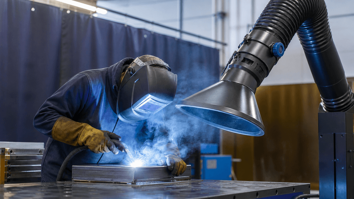
Welding fume rises, curls, and drifts. It can be pulled by an extraction arm, pushed by a cooling fan, blocked by a fixture, or carried through the worker's breathing zone before it reaches any hood. A welding fume extraction system should be designed around this movement, not around a fixed point on the wall.
Start by observing every common weld position: flat seams, vertical seams, tack welds, rework, robotic welds, positioner work, and maintenance welding. Watch where the welder's head sits relative to the plume. Check whether a curtain, fixture, part edge, or open door changes airflow. A system that captures during one neat test weld may miss fume during the awkward welds that happen every shift.
NAROO's laser processing application context is relevant because fine fume and particulate generated by high-energy work need close capture and dependable filtration. In automotive production, tailored air filtration and dust removal systems are also tied to real cell layout, not just equipment capacity.
Manual Welding Depends on Usability
Flexible arms and portable extraction units can be effective when the operator keeps the hood close to the arc. The difficulty is daily use. If the arm is heavy, hard to position, always in the way, or too short for the job, workers will naturally move it aside. The system then becomes a nice installation photo rather than a real exposure-control tool.
For manual welding, involve welders in mockups before final layout. Ask whether the hood blocks sightlines, access, torch angle, clamp movement, or part handling. A small repositioning handle, better arm reach, or side baffle can make the difference between a control that is used and a control that is avoided.
Training should be visual and specific. A smoke test can show why the hood must stay close to the plume. A photo of good and poor hood position can help supervisors coach the habit. The goal is not to blame the welder; it is to give the welder a control that fits the work.
Robot Cells Need Commissioning After Program Changes
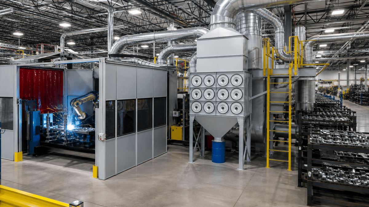
Robotic welding removes some operator variability, but it does not remove ventilation questions. The plume may be repeatable during one robot program and different after the path, speed, fixture, part size, or weld sequence changes. Enclosure doors, service openings, and part loading zones also affect containment.
Commissioning should include normal production speed, door openings, part loading, robot dwell, and maintenance positions. If the cell is enclosed, inward airflow through openings should be verified. If fume is extracted from the top of the cell, check whether heat carries the plume upward before it leaks through door gaps. If capture is built into the torch or fixture, confirm that shielding gas and weld quality are not disturbed.
Robot cells benefit from records. Keep airflow readings, filter pressure trends, robot program notes, visible fume observations, and maintenance findings together. When production changes, the extraction system should be rechecked rather than assumed to behave the same way.
Filtration Must Match the Welding Stream
Welding fume can contain very fine particulate from base metal, filler metal, coatings, fluxes, and surface contamination. Stainless steel welding, galvanized material, painted parts, and coated assemblies can create different exposure and filtration concerns. Before choosing the collector, identify the materials and consumables.
For many fine dry fume applications, NAROO's cartridge dust collector category is relevant because the site positions cartridge systems around fine particle filtration, surface filtration, pulse-jet cleaning, and airflow resistance calculation. An industrial cartridge dust collector can support a welding fume extraction system when the stream and safety review fit dry particulate filtration.
However, the collector should not be asked to solve incompatible streams. Sparks, grinding dust, oil mist, solvent vapor, and combustible dust may require separation or additional controls. If the process includes coatings or solvent-related emissions, particulate filtration should not be confused with VOCs Control. Gas-phase treatment is a separate engineering question.
Do Not Let Shielding Gas Become the Hidden Tradeoff
A welding fume extraction system must remove fume without damaging the weld process. Too much airflow at the arc can disturb shielding gas in some welding methods. Too little airflow lets fume escape. The correct balance depends on hood distance, nozzle type, weld method, part shape, and air movement in the cell.
This balance should be tested during actual welds. Look for weld quality issues, porosity concerns, plume escape, and operator complaints. A system that improves visible capture but harms welding performance will not survive long in production. A system that protects welding quality but misses the plume also fails its purpose. Practical commissioning respects both.
Maintenance Is Part of Exposure Control
Captured fume becomes collected residue. Filter changeout, dust drawer emptying, duct cleaning, and collector service should be planned as controlled maintenance tasks. Fine welding residue should not be shaken loose into the shop during service. Workers need access space, suitable PPE, waste containers, and a procedure that does not undo the source capture achieved during production.
Pressure drop should be logged at consistent production states. If pressure rises faster after a material change, the filters may be loading differently. If pressure drops suddenly, inspect for damaged media, poor seals, open access doors, or bad sensing lines. The gauge is useful only when paired with visible capture checks and work-cell observations.
NAROO's industrial dust collection product range helps frame these decisions across cartridge collectors, bag collectors, cyclone pre-separation, and wet collection paths. For supplier evaluation, the company profile supports a system discussion from design through installation.
Retrofits Need More Discipline Than New Cells
Retrofitting a welding fume extraction system into an existing shop can be harder than designing a new cell. Existing benches, cranes, gas lines, electrical drops, tool carts, curtains, and walkways may block the best hood locations. The duct route may be longer than ideal. Production may need to continue while installation occurs. These constraints should be named early so the project does not become a compromise hidden inside a quotation.
A retrofit survey should include ceiling height, structure, door locations, cross-drafts, current fans, existing collectors, and maintenance access. It should also include the work that happens outside the normal station: rework, repair welding, fixture cleanup, and occasional large parts. These tasks often create fume complaints because they are not served by the original extraction layout.
If the plant cannot install the ideal hood position, the design may need partial enclosure, movable capture, dedicated portable extraction, or changes to the work method. A realistic retrofit accepts the constraints and then verifies the result during production.
Exposure Data Closes the Loop
Visible fume is useful, but exposure data gives the EHS team a stronger basis for decisions. If the materials or process raise concerns such as manganese, stainless steel fume, galvanized coatings, or hexavalent chromium, personal sampling and qualified review may be needed. Ventilation performance should be read together with that exposure information, not treated as a separate maintenance topic.
When exposure results improve after hood changes, training, or filtration upgrades, the plant gains evidence that the system is doing useful work. When results remain high, the team can look at plume path, welder position, cross-drafts, task duration, and respiratory protection requirements. This feedback loop is what turns a welding fume extraction system from a purchased asset into a managed control.
What to Give a Supplier Before Quoting
- Welding process, base metals, filler metals, coatings, and surface contaminants.
- Photos or video of the plume during normal welds and awkward welds.
- Worker position, robot path, fixture geometry, and part size.
- Current hood, duct, fan, and filter information if replacing a system.
- Known exposure concerns such as manganese, hexavalent chromium, or coated materials.
- Whether air will discharge outdoors or return indoors after filtration.
- Maintenance access, filter change frequency, and pressure drop history.
Conclusion
A welding fume extraction system works when it follows the weld plume, fits the operator or robot cell, protects the breathing zone, preserves weld quality, and keeps maintenance controlled. The collector matters, but source capture decides whether the fume enters the system in the first place. Start with the weld, then design the airflow around the work. Review the setup again whenever parts, materials, fixtures, or work practices change.